What Is a Steel Cable Tray and How Does It Work?
A Steel Cable Tray is an engineered support system for organizing and protecting electrical, control, and communication cables. It usually consists of steel sections, fittings, covers, and connection hardware. Common designs include ladder, perforated, and solid-bottom trays. Each design responds to different ventilation, protection, and cable-management needs.
It is not simply a shelf. In practical installations, the tray carries cables above floors, along walls, or beneath ceilings. Its open structure can improve airflow and make inspection easier. Technicians can trace a cable, add a route, or identify damage without disturbing an entire bundle. Galvanized steel often suits general industrial environments, while stainless steel may perform better where moisture or chemicals create corrosion concerns. Details matter. Tray width, load capacity, support spacing, bend radius, and fastening methods must match the installation conditions. Poor planning can cause sagging, sharp bends, overheating, or difficult maintenance later. Grounding and bonding also require careful attention, although the tray should not automatically be treated as the only grounding path. A reliable design follows manufacturer data and applicable electrical standards. Site experience shows that small oversights, such as crowded bends or missing covers, can become expensive problems. Still, no cable tray solves every routing challenge. Engineers must consider fire separation, access, expansion, corrosion, and future cable growth. This article explains how a Steel Cable Tray works and why its construction influences safety, durability, and maintenance. It also questions a common assumption: stronger steel alone does not guarantee a better cable-management system.
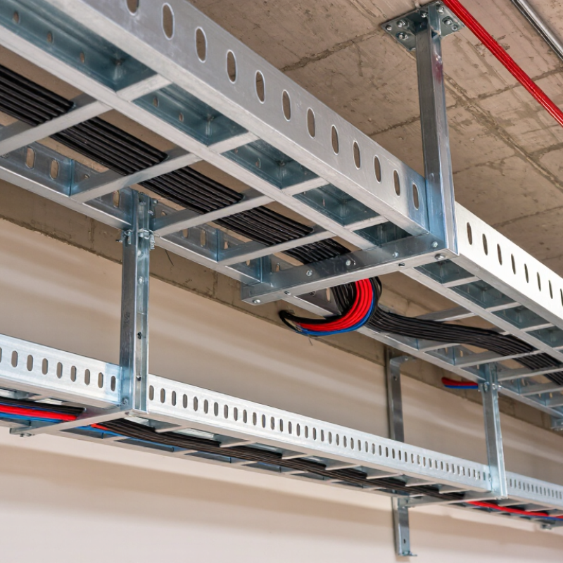
What Is a Steel Cable Tray?
A steel cable tray is a structured support system for electrical and communication cables. It usually consists of steel side rails, cross members, and a protective finish. Common designs include ladder trays, perforated trays, and solid-bottom trays. Each design manages cables differently.
In practical installations, the tray runs along walls, ceilings, or service corridors. Cables rest inside the tray instead of hanging loosely or pressing against sharp building edges. Ladder trays improve ventilation around power cables. Perforated trays offer extra support for smaller cables. Solid-bottom trays protect sensitive wiring from falling dust and minor impacts.
Steel provides strong mechanical support. Galvanized steel resists moisture and surface corrosion in many indoor and semi-outdoor areas. Stainless steel suits harsher environments, especially where cleaning chemicals or salt exposure may occur. The correct material depends on temperature, humidity, cable weight, and local installation requirements.
A steel tray is not a complete safety system by itself. Installers must check load capacity, support spacing, cable separation, and bonding connections. Poor spacing can cause sagging. Weak bonding can create electrical risks. It is easy to assume every tray works the same way, but that assumption needs checking. Real sites often contain tight corners, uneven supports, and unexpected heat sources. Careful measurement and regular inspection make the system more dependable.
What Is a Steel Cable Tray and How Does It Work?
Steel cable trays support and route electrical cables while allowing ventilation and easier inspection. This chart compares the gross cross-sectional area of common tray widths using a 100 mm tray depth with a 40% planning allowance for cable occupancy. Actual allowable fill and load capacity depend on the tray design, cable type, support spacing, and applicable installation standards.
How Is a Steel Cable Tray Designed and Constructed?
A steel cable tray is designed as a continuous support system for power, control, and communication cables. Engineers begin by calculating cable weight, tray span, support spacing, and expected future capacity. A practical design often reserves space for additional cables, though this allowance is sometimes underestimated. The tray width and side-rail height must prevent crowding and excessive heat buildup. Load tables help determine the required steel thickness and maximum unsupported span.
Construction usually starts with galvanized or coated steel sheet. The sheet is cut, punched, and formed into ladder, perforated, or solid-bottom sections. Rails and rungs may be welded or mechanically joined. Smooth edges matter because sharp metal can damage cable jackets during installation. Splice plates, bolts, and brackets connect each section into a stable pathway. In demanding areas, designers may specify heavier sections or closer supports.
Surface protection depends on the environment. Galvanizing suits many indoor and outdoor installations, while additional coatings may help in humid or chemically aggressive locations. Installers must bond adjoining sections and connect the tray to the grounding system where required. Expansion joints can accommodate temperature movement on long runs. Field conditions often differ from drawings, so support locations may need careful adjustment. That adjustment should be documented, not guessed. A strong tray system is not merely metal shaped into a channel; it is a coordinated structure built around load, access, safety, and service conditions.
How Does a Steel Cable Tray Support and Route Cables?
What Is a Steel Cable Tray and How Does It Work?
How Does a Steel Cable Tray Support and Route Cables?
A steel cable tray supports electrical and communication cables above floors, ceilings, or equipment areas. Its open structure keeps cables organized and accessible. Unlike closed conduits, it allows technicians to inspect cables without removing long covers. Steel rails and cross members carry the cable weight across planned support points.
During installation, engineers select the tray width, depth, and material thickness according to cable quantity and load. Supports are commonly fixed to walls, ceilings, or structural steel at calculated intervals. Straight sections create the main route, while bends, tees, and reducers guide cables around columns and equipment. Cables should rest evenly, not pile sharply against one side. Small details matter.
The tray also helps control cable movement during maintenance and future expansion. Proper bonding and grounding reduce unwanted electrical risk when required by applicable codes. Separating power, control, and sensitive communication cables can limit interference. I have seen crowded trays become difficult to service, even when the original design looked adequate. A little spare capacity usually prevents that problem. Still, “more space” is not always better; oversized trays can waste material and complicate support design. Installers must check sharp edges, fastener security, corrosion exposure, and the actual cable radius before pulling cables through.
What Are the Main Types and Applications of Steel Cable Trays?
A steel cable tray is a support system for routing and protecting electrical cables. It uses a formed steel pathway instead of closed conduit. Cables rest on the tray and remain accessible for inspection, testing, or replacement. In field installations, this access can save hours during maintenance.
Ladder trays have two side rails connected by rungs. They provide strong support and excellent ventilation for power cables. Perforated trays use a continuous base with openings, offering better support for smaller control cables. Solid-bottom trays protect cables from dust, falling particles, and dripping liquids. Wire-mesh trays are lighter and useful for data, communication, and low-voltage systems. Each type fits a different working condition.
Applications depend on load, environment, and maintenance needs. Manufacturing plants often use ladder trays for large motors and feeder cables. Data rooms may use wire-mesh or perforated trays for organized network cabling. Commercial buildings commonly install steel trays above ceilings or beneath raised floors. Galvanized steel suits many indoor and outdoor areas, while stainless steel performs better in corrosive environments. Poor spacing can still cause heat buildup. I have seen crowded trays complicate fault tracing, even when the original installation passed inspection. Engineers should check cable weight, bend radius, grounding continuity, and expansion points before installation. The practical choice is not always the cheapest one.


