How to Choose the Right Inverter Inductor in 2026

Choosing the right Inverter Inductor in 2026 will require more than matching inductance and current ratings. Solar farms, battery systems, electric vehicles, and industrial drives are demanding quieter, cooler, and more efficient power conversion. The International Energy Agency’s Renewables 2024 report expects global renewable capacity to expand by almost 5,500 GW between 2024 and 2030. That growth will increase demand for reliable filtering and energy-storage components inside modern inverters.

The pressure is real. Component selection now affects efficiency, thermal stability, electromagnetic interference, acoustic noise, and service life. An undersized Inverter Inductor may saturate during a sudden load change. Excessive core loss can create a hot spot near the winding window. A larger part may reduce ripple, yet consume valuable cabinet space. Professor Frede Blaabjerg, a leading power-electronics researcher, has described power electronics as “the key technology in the future energy system.” His point remains practical: small magnetic components can influence the performance of an entire system.

This guide examines core material, saturation current, ripple frequency, winding construction, cooling, and certification requirements. It also considers supplier consistency and lifecycle data, which engineers sometimes overlook. Reports from IEA, DNV, and major power-electronics research groups show a market moving toward higher switching frequencies and denser designs. Still, no spreadsheet captures every vibration, temperature cycle, or installation mistake. That is the uncomfortable part. The best Inverter Inductor is not always the smallest, cheapest, or most efficient on paper. It is the component that remains stable when real conditions become less cooperative.
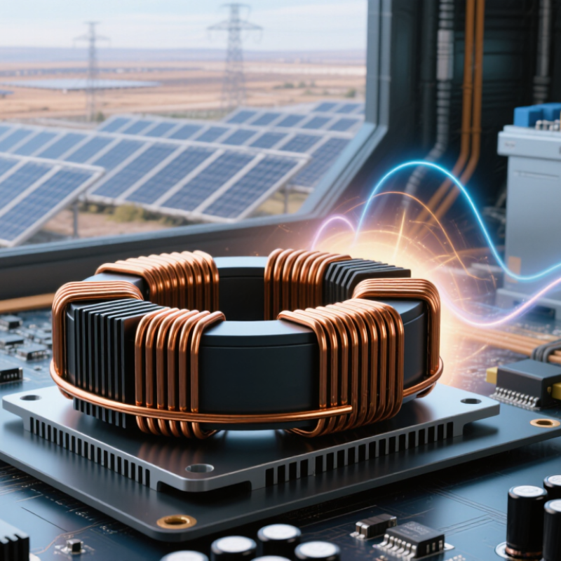
How to Choose the Right Inverter Inductor in 2026

Understand the Role of an Inductor in an Inverter

How to Choose the Right Inverter Inductor in 2026

An inductor is the inverter’s quiet energy buffer. It stores energy, limits current ripple, and filters rapid switching pulses before they reach the load or grid. In a 2026 design, this role matters more as renewable installations expand. IRENA’s Renewable Capacity Statistics 2024 reported 473 GW of new renewable capacity in 2023, representing 86% of total global power additions. More converters mean more demanding thermal and electromagnetic conditions.

Key selection considerations

During selection, match inductance to switching frequency, peak current, and allowable ripple current. A higher inductance can reduce ripple, but it may increase size, cost, and stored energy. The magnetic core must also avoid saturation during short overloads. Check the saturation curve, not only the rated current. It gets overlooked. Core loss rises with frequency, while copper loss grows with RMS current. Both losses create heat inside a compact enclosure.

The IEA’s Renewables 2024 analysis highlights continued growth in solar and storage deployment, pushing designers toward smaller, faster inverters. That trend makes material choice important. Ferrite may suit higher frequencies, while powdered cores can tolerate distributed air gaps. Verify temperature rise through testing, because datasheet values often assume ideal airflow. I still see designs selected from nominal current alone. That shortcut can fail during cold starts, fault recovery, or uneven cooling. Reviewing IEC requirements, waveform measurements, and worst-case simulations provides stronger evidence than relying on one catalog number.

Identify the Electrical and Operating Requirements

How to Choose the Right Inverter Inductor in 2026: Identify the Electrical and Operating Requirements

Start with the inverter’s DC-link voltage, output current, switching frequency, and allowable ripple current. These values define the inductance and current rating the design needs. Check the maximum current during startup and load changes, not just the steady-state value. The inductor’s saturation current must exceed those peaks; otherwise, inductance can fall just when the circuit needs it most. Also confirm winding resistance and core losses at the actual switching frequency. The U.S. Department of Energy’s SunShot Vision Study used 97% inverter efficiency as a historical target. That benchmark shows why even small component losses deserve attention, though it is not a universal requirement for every inverter.

Then match the part to its real operating environment. Estimate temperature rise inside the enclosure, including nearby hot components and limited airflow. Compare the inductor’s rated temperature with the expected ambient and winding temperatures. Review insulation requirements, vibration exposure, and available mounting space. A compact part may fit neatly, yet run hotter under sustained load. That trade-off is easy to underestimate.

Compare Core Materials, Inductance, and Current Ratings

How to Choose the Right Inverter Inductor in 2026

Core material affects losses, heat, size, and behavior under changing current. Ferrite cores often suit higher switching frequencies because they can keep core losses manageable. Powdered iron cores may offer a gradual response to overload, but their losses can rise in some operating conditions. Check material data at your inverter’s actual frequency and temperature, not just at room temperature. Small details matter.

Choose inductance based on the circuit topology, switching frequency, ripple-current target, and input or output range. Too little inductance can produce excessive ripple and stress nearby components. Too much may slow response or require a larger, heavier part. Use the design equations as a starting point, then verify performance across expected operating conditions. Measure twice.

Current ratings need careful interpretation. A saturation rating indicates when inductance begins to fall, while a thermal rating reflects allowable heating under specified conditions. Neither number alone guarantees safe operation in your design. Compare peak current with the saturation limit, and check RMS current against the thermal rating. Also consider airflow, copper resistance, and nearby heat sources. It is tempting to choose the smallest inductor that meets the table values; that shortcut can leave little margin during startup or load changes. Recheck temperatures in the assembled inverter, where real airflow may differ from a test setup.

Assess Thermal Performance, Losses, Size, and Mounting

How to Choose the Right Inverter Inductor in 2026

Thermal performance is more than a maximum-temperature figure. Check the rated current, ambient temperature, airflow, and temperature rise together. A coil that runs cool on an open test bench may heat up inside a sealed cabinet. Measure temperatures near the winding and core under realistic load. Hot spots matter.

Losses shape both efficiency and cooling needs. Compare copper loss at the actual switching frequency, not just the catalogue’s headline current. Core loss can climb as frequency and ripple increase. The International Energy Agency’s Global EV Outlook 2024 reports that electric car sales reached nearly 14 million in 2023, increasing demand for compact, high-power conversion equipment. That is useful context, not an inductor performance benchmark. Ask suppliers for test conditions and loss curves; data without conditions is hard to trust.

Size and mounting affect reliability, too. Check clearance around the part, creepage requirements, vibration, and how securely the core sits on the board or chassis. A smaller footprint can restrict airflow or complicate assembly. Not always an upgrade. In prototypes, inspect solder joints and mounting hardware after thermal cycling and vibration tests. These checks take time, and they may still miss a real-world resonance or installation issue. That uncertainty deserves attention.

How to Choose the Right Inverter Inductor in 2026 — Assess Thermal Performance, Losses, Size, and Mounting
Example design profile Inductance and rated RMS current Winding DCR and estimated copper loss Thermal performance to verify Core-loss assessment Approximate package size (L × W × H) Typical mounting approach Selection notes
Compact auxiliary or low-power inverter 100 µH; 10 A RMS 18–25 mΩ; approximately 1.8–2.5 W at 10 A Check temperature rise at the intended ambient temperature and airflow; keep winding and core temperatures within their specified limits. Compare material-specific loss data at the actual switching frequency and peak flux density. Confirm that saturation does not occur at peak current. Approximately 30 × 30 × 20 mm PCB through-hole pins or a mechanically secured chassis mount, depending on mass and vibration requirements. Useful where board area is limited and ripple-current requirements allow the higher inductance.
General-purpose single-phase inverter 68 µH; 20 A RMS 7–10 mΩ; approximately 2.8–4.0 W at 20 A Check the manufacturer’s current-rating test conditions, including ambient temperature, PCB copper, and airflow; these conditions vary between designs. Evaluate core loss and winding AC loss at the intended frequency and waveform. A DC-resistance value alone does not predict total inductor loss. Approximately 40 × 40 × 25 mm Through-hole PCB mounting with nearby mechanical support, or a bolted base for heavier constructions. A balanced starting point for moderate current; verify inductance under DC bias as well as at small-signal test conditions.
Higher-current motor-drive inverter 47 µH; 35 A RMS 3–5 mΩ; approximately 3.7–6.1 W at 35 A Allow for winding hot spots and enclosure temperature. Validate the complete assembly under representative load and airflow. Check core-loss curves at the operating flux swing and switching frequency; assess proximity and skin-effect losses in the winding at higher frequencies. Approximately 50 × 50 × 30 mm Bolted chassis or baseplate mounting, with short, wide electrical connections and vibration-resistant hardware. Consider parallel winding paths or a suitable conductor construction where AC winding loss is significant.
High-current power-conversion stage 33 µH; 50 A RMS 1.5–2.5 mΩ; approximately 3.8–6.3 W at 50 A Use thermal measurements or validated thermal analysis at worst-case ambient and load; account for nearby heat sources and restricted airflow. Request loss data for the intended frequency, flux density, and temperature. Confirm that peak current remains below the specified saturation limit. Approximately 60 × 60 × 35 mm Rigid chassis or baseplate mounting; design terminals and busbars for current, temperature rise, and mechanical stress. Low DCR can reduce conduction loss, but the larger current and core may increase size and stored energy; check switching-ripple and fault-current requirements.

The profiles and figures above are illustrative engineering screening examples, not specifications for particular products. Copper-loss estimates use P = I² × DCR and exclude core loss, AC winding loss, and connection losses. Final selection should use the candidate’s datasheet and be validated at the actual switching frequency, ripple and peak current, ambient temperature, cooling conditions, and mounting arrangement.

Verify Compatibility, Safety Standards, and Long-Term Reliability

How to Choose the Right Inverter Inductor in 2026

Verify Compatibility, Safety Standards, and Long-Term Reliability

An inductor that fits the board may still be wrong for the inverter. Match its inductance and saturation-current rating to the switching frequency, peak current, and expected temperature range. Check RMS ripple current and winding resistance, too: both affect heat inside a crowded enclosure. Small margins matter. A part tested at room temperature may behave differently beside a hot switching device.

IEA PVPS reported 456 GW of new photovoltaic capacity worldwide in 2023, underscoring the scale of equipment expected to operate reliably across varied conditions.

Review the complete datasheet, not just the headline current rating. Confirm insulation and creepage requirements against the converter’s working voltage, and assess the finished design against IEC 62477-1 safety requirements where applicable. Ask for temperature-rise, vibration, and humidity test results that reflect the actual installation. Then measure inductor temperature and ripple current on a prototype under worst-case load. A datasheet can still leave gaps, especially around airflow and nearby heat sources; that part needs engineering judgment. Record the test conditions, since “passed” means little without them.

×
img

    Contact Info

    PHONE NUMBER

    +1 (619) 661-5985

    EMAIL ADDRESS

    sale@roboticemotion.com

    ADDRESS INFO

    10030 Via de la Amistad San Diego CA 92154, United States